March 18th, 2024 11:39PM EDT
1(888)626-4365
Lynch Fluid Controls logo
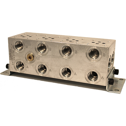
LYNCH BAR MANIFOLDS & ACCESSORIES
Standard Bar Manifold

STANDARD SPECIFICATIONS

Standard Materials:
Aluminum-6061T6 and Ductile-654512
Other Material Options:
Mild Steel or Stainless Steel
Maximum Pressure:
Alu 3,000 PSI, Duc 5,000 PSI
Special Finishes:
Black Oxide, Electroless Nickel Plating, Anodizing
Mounting:
4 Bolt mount design; for vertical mounting or with foot bracket

APPLICATIONS

Tunnel boring Machine
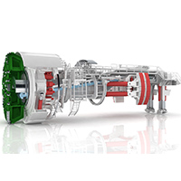
Tunnel Boring Machines - Different sizes of Lynch Bar Manifolds are used to control the Drill Carriage, Erector Slide, Clamps, and many more hydraulic devices inside these big and remarkable machines. Each station controls the direction of one movement, its speed and its force with different modular valves depending on the different requirements.
Testing station
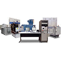
Test Stands - Lynch Bar Manifolds are being used to test Airplane Landing Gears. One station controls the hydraulic actuator pushing the landing gear towards the front while a second one pushes to the side. Both cylinders use the same pump but they need different speeds and pressures, so each station has different controls mounted in sandwich bodies under the directional valves.

BAR MANIFOLDS
Shop Now

Lynch bar manifolds have a similar look to what the industry is accustomed, but are enhanced to maximize performance while accommodating the highest number of standard options in a more uniform and easier-to-install package. We looked beyond established layouts and developed a series of stringent design parameters to configure our products. Bar Manifolds reduce plumbing, number of leak points, and improve the appearance and maintenance of the hydraulic system by centralizing the location of the valves. Directional control valves change the direction of fluid flow. These patterns usually have oil passage holes with options for X & Y ports. Threaded or flanged ports provide the user connections with manifolds.

FEATURES AND BENEFITS

  • Bar manifolds are designed to have the highest flow rate and lowest pressure drop in the industry.
  • Internal galleries are equal to or greater than the nominal port connection in order to minimize pressure drops and fluid velocities.
  • Port spacing and edge distance has been maximized to ensure easier installation and servicing.
  • Common drain ports, are supplied on both ends of the manifold for ease of installation and connecting a series of manifolds without the need of tees and elbows.
  • P to T Relief cavities in Sun and Common Cavity form are standard options, while the ISO and other types are non-standard options.
  • No variation in the design layout for each Model regardless of Port Code.
  • Manifolds with Flange Ports are available with UNC mounting threads and SAE Ports or with Metric mounting threads and Metric Ports as standard.
  • "P" and "T" port isolations are available for manifolds up to 10 stations. A second gauge port is provided with "P" port isolations when possible.
  • UNC or Metric mounting bracket kits come standard with all bar manifolds.
  • Stud rods are available ranging in sizes from ISO 03 to ISO 08 simplify installation & save you money.
  • Distributors Dream – Stocking our product is a breeze.
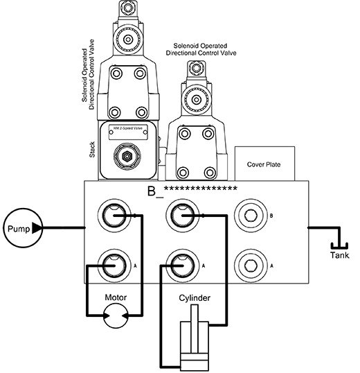
BLOCK DIAGRAM

Bar block diagram

BUILD A BAR MANIFOLD

Type
Type:
Unselected
-
Unselected
-
Bar Manifold
B
Material
Material:
Unselected
-
Unselected
-
Aluminum
A
Ductile Iron
D
Valve Pattern
Valve Pattern:
Unselected
---
Unselected
---
D02 - ISO 4401-02-01 / NFPA T3.5.1
02G
D03 - ISO 4401-03-02 / NFPA T3.5.1
03G
D05 - ISO 4401-05-04 / NFPA T3.5.1
05G
D05 (Dual Tank) - ISO 4401-05-04 / NFPA T3.5.1
05T
D05 Alt B - (USA Standard) NFPA T3.5.1
05H
D05 Alt A - ISO 4401-05-05 (EURO) / NFPA T3.5.1
05E
D07 - ISO 4401-07-06 / NFPA T3.5.1
07G
D08 - ISO 4401-08-07 / NFPA T3.5.1
08G
D10 - ISO 4401-10-08 / NFPA T3.5.1
10G
Circuit, Capacity & Spacing
Circuit, Capacity & Spacing:
Unselected
--
Unselected
--
Parallel circuit Standard Flow Std. Spacing
PS
Parallel cicuit Standard Flow Wide Spacing
PT
Parallel circuit High Flow Std. Spacing
PH
Parallel circuit High Flow Wide Spacing
PI
Parallel circuit Very High Flow Std. Spacing
PV
Parallel circuit Very High Flow Wide Spacing
PW
Parallel circuit Standard Flow Std. Spacing (Bottom Ported)
AS
Parallel circuit Standard Flow Wide Spacing (Bottom Ported)
AT
Parallel circuit High Flow Std. Spacing (Bottom Ported)
AH
Parallel circuit High Flow Wide Spacing (Bottom Ported)
AI
Series circuit Standard Flow Std. Spacing
SS
Series cicuit Standard Flow Wide Spacing
ST
Std. NO. of Stations
Std. NO. of Stations:
Unselected
--
Unselected
--
1 Station
01
2 Stations
02
3 Stations
03
4 Stations
04
5 Stations
05
6 Stations
06
7 Stations
07
8 Stations
08
9 Stations
09
10 Stations
10
11 Stations
11
12 Stations
12
13 Stations
13
14 Stations
14
15 Stations
15
16 Stations
16
Port Code
Port Code:
Unselected
--
Type
A & B
Code
Unselected
--
--
SAE
6
SC
NPTF
3/8"
NC
BSPP
3/8"
BC
BSPT
3/8"
TC
METRIC
M14
MC
SAE
8
SD
NPTF
1/2"
ND
BSPP
1/2"
BD
BSPT
1/2"
TD
METRIC
M18
MD
SAE
12
SF
NPTF
3/4"
NF
BSPP
3/4"
BF
BSPT
3/4"
TF
METRIC
M27
MF
SAE
16
SH
NPTF
1"
NH
BSPP
1"
BH
BSPT
1"
TH
METRIC
M33
MH
SAE
20
SI
NPTF
1 1/4"
NI
BSPP
1 1/4"
BI
BSPT
1 1/4"
TI
METRIC
M42
MI
SAE CODE 61
3/4"
1F
SAE CODE 61
1"
1H
SAE CODE 61
1 1/4"
1I
SAE CODE 61
1 1/2"
1J
Mounting Threads & Kit
Mounting Threads & Kit:
Unselected
-
Unselected
-
UNC Std for SAE & NPT
U
Metric Std for BSP & Metric
M
UNC Std for SAE & NPT (4 Bolt)
F
Metric Std for BSP & Metric (4 Bolt)
G
Relief Cavity
Relief Cavity:
Unselected
-
Unselected
-
None
A
Sun T-10A
C
Common C10-2
D
Sun T-3A
E
Sun T-16A
G
Common C16-2
H
Sun T-18A
I
Pilot Port Options
Pilot Port Options:
Unselected
-
Unselected
-
None
A
Common Y
B
Common Y & Indep X
C
Common Y & X
D
P Port Isolation
P Port Isolation:
Unselected
-
Unselected
-
None
A
01-02: Left or None
B
02-03: Left or None
C
03-04: Left or None
D
04-05: Left or None
E
05-06: Left or None
F
06-07: Left or None
G
07-08: Left or None
H
08-09: Left or None
I
09-10: Left or None
2
10-11: Left or None
3
11-12: Left or None
4
01-02: Right
J
02-03: Right
K
03-04: Right
L
04-05: Right
M
05-06: Right
N
06-07: Right
O
07-08: Right
P
08-09: Right
Q
09-10: Right
5
10-11: Right
6
11-12: Right
7
01-02: Both Sides
R
02-03: Both Sides
S
03-04: Both Sides
T
04-05: Both Sides
U
05-06: Both Sides
V
06-07: Both Sides
W
07-08: Both Sides
X
08-09: Both Sides
Y
09-10: Both Sides
Z
10-11: Both Sides
8
11-12: Both Sides
9
T Port Isolation
T Port Isolation:
Unselected
-
Unselected
-
None
A
01-02: Left or None
B
02-03: Left or None
C
03-04: Left or None
D
04-05: Left or None
E
05-06: Left or None
F
06-07: Left or None
G
07-08: Left or None
H
08-09: Left or None
I
09-10: Left or None
2
10-11: Left or None
3
11-12: Left or None
4
01-02: Right
J
02-03: Right
K
03-04: Right
L
04-05: Right
M
05-06: Right
N
06-07: Right
O
07-08: Right
P
08-09: Right
Q
09-10: Right
5
10-11: Right
6
11-12: Right
7
01-02: Both Sides
R
02-03: Both Sides
S
03-04: Both Sides
T
04-05: Both Sides
U
05-06: Both Sides
V
06-07: Both Sides
W
07-08: Both Sides
X
08-09: Both Sides
Y
09-10: Both Sides
Z
10-11: Both Sides
8
11-12: Both Sides
9
Welcome to the Part Number Generator
The part number you have selected is only available by special order. Please contact your Lynch representative for more details.
The part number you have selected is not a standard configuration. Please contact your Lynch representative for more details.
Lynch Headquarters Mississauga on map.
Canada
1799 Argentia Road
Mississauga, Ontario, L5N 3A2
Lynch Headquarters New York on map.
U.S.A.
3790 Commerce Court Suite 500,
North Tonawanda, New York, 14120